ISO 9001 · ISO 14001 · ISO 45001 · CE · UDEM · EAC · CQC
🇮🇩 Indonesia · Mining
Indonesia: 20 kV/0.4 kV Containerized Mining Substation
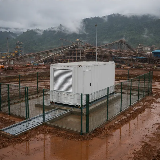
Reference configuration: 20 kV/0.4 kV containerized prefabricated substation for remote mining and mineral-processing facility in Indonesia — 20 kV incoming…
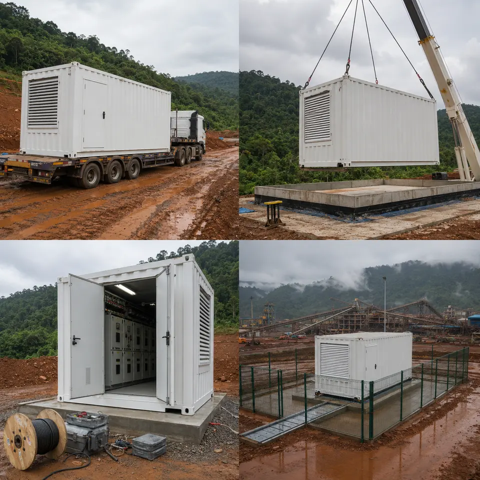
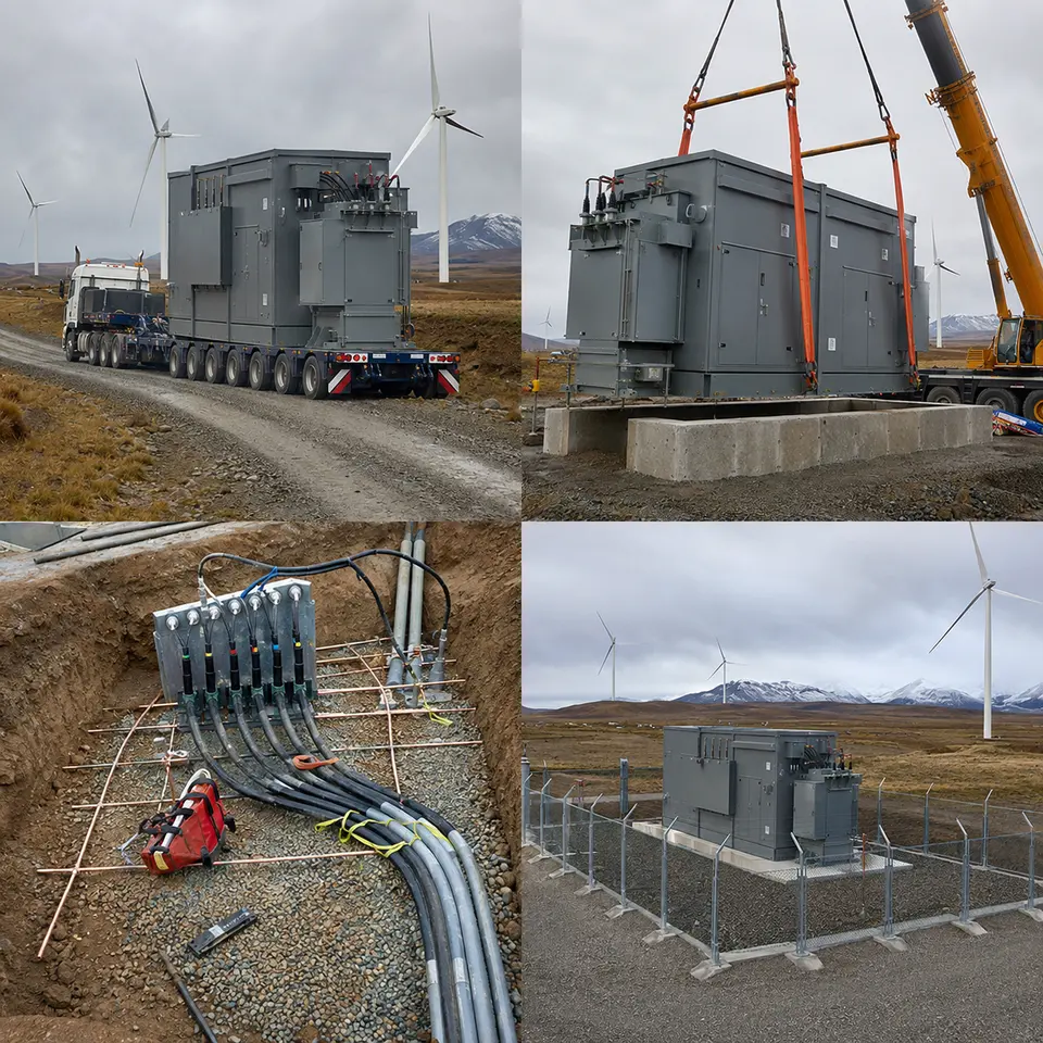
Four-stage build sequence typical of a containerized 20 kV substation supplying an Indonesian mining site
Representative project visualisation. Representative visualisation only. Every image in this set is a representative rendering of a typical build for this equipment class — not a photograph, and not documentary proof that a specific project was completed. No particular customer, mine, operator, contract, commissioning date or third-party sign-off is being represented here. The ratings, quantities and layout shown are illustrative examples that would be pinned down against an actual enquiry.
Indonesia's medium-voltage grid delivers power at 20 kV, and a mine or mineral-processing plant typically sits at the far end of that network, well beyond same-day reach of a service crew. That single fact drives four separate design conclusions.
The first concerns labour. Fieldwork on a remote site is slow, costly and hard to inspect, so shifting as much of the build as possible into the factory pays off directly. A containerized substation arrives already assembled and function-tested, which turns weeks of site electrical work into days of positioning and termination.
The second concerns the load itself. Crushers, mills, conveyors and pumps are motor loads that pull heavy starting current, and where drives are fitted they also push harmonic current back onto the supply. This forces a compromise on transformer impedance: low enough that voltage does not collapse during a large motor start, yet high enough to keep prospective fault current inside what the LV switchgear can withstand. There is no shortcut here — the right number comes from the plant's actual motor list, not a default.
The third concerns climate and geology working together. Humidity and monsoon downpours turn condensation and water ingress into the leading threats to anything inside the enclosure; mineral dust abrades surfaces and, depending on the ore, can be conductive or moisture-absorbing; and the roads in are frequently wet and rutted. Keeping the interior dry therefore rests on a raised plinth, properly sealed cable glands, managed ventilation and anti-condensation heaters. Because Sulawesi also carries meaningful seismic risk, how the enclosure and its internal equipment are anchored has to be engineered up front rather than left to whoever installs it.
A fourth, less obvious requirement is the ability to move the asset again later. Mining loads shift as pits and processing needs change, and a container built to be re-lifted and re-sited will outlast a fixed masonry substation in practical terms.
System configuration
Item
Description
Specification notes
Container enclosure
Factory-assembled, weatherproof outdoor substation housing, mounted on a skid or concrete plinth
IP rating and ISO 12944 coating category chosen for tropical humidity, rainfall and mineral dust; lifting and re-lifting points designed in from the outset
MV switchgear
Switching and protection for the 20 kV incoming and outgoing circuits
SF6-insulated or solid-insulated ring main unit, or air-insulated metal-clad panels when future extension and withdrawable breakers are wanted; internal arc classification matched to the room layout
Transformer
Distribution transformer stepping 20 kV down to 0.4 kV
Cast-resin dry-type where fire load inside the container needs to be kept low, or oil-immersed with containment; impedance selected against motor-starting behaviour and LV fault withstand
LV distribution
LV main board plus motor and feeder outgoing ways
Built to IEC 61439-1/-2; form of separation and short-circuit withstand set by the plant's fault level and maintenance approach
Protection
MV overcurrent and earth-fault relaying, plus LV main and feeder protection
Grading coordinated across the MV, transformer and LV stages; earth-fault sensitivity matched to the earthing arrangement in use
Ventilation and thermal control
Filtered forced ventilation or air conditioning, plus anti-condensation heating
Capacity sized against total equipment losses at design ambient; filtration specified to cope with abrasive mineral dust
Sealed entries preserve the enclosure's IP rating; non-magnetic gland plates used for single-core LV cables
Earthing
Internal earth bar, bonding of enclosure and equipment, connection to an external electrode
Conductor sized for the prospective earth-fault current and its clearing time; step and touch potential verified for an outdoor, publicly accessible location
Monitoring and communication
Temperature, door, alarm and status contacts, with an optional gateway
Modbus RTU/TCP, IEC 61850 or DNP3 available where equipment of this kind reports into a mine-wide control system
Installation sequence
Overview — Four-stage build sequence typical of a containerized 20 kV substation supplying an Indonesian mining site
This contact sheet lays out the four stages a project of this kind moves through: transport to site, the crane lift onto its raised base, the internal switchgear and cabling work, and the finished, closed-up installation. Access dictates the order here. The foundation, the earth electrode and the drainage all have to be finished and checked out before the container arrives, since nothing underneath it can be reached once it is set down. Cable routing is only finalised after the unit is in position, so lengths are cut to the actual layout rather than a drawing. Any testing that needs panels open happens before the compound is fenced and closed off. On a site this remote, each stage also has to work around the weather, because a flooded access road can stop the whole schedule.
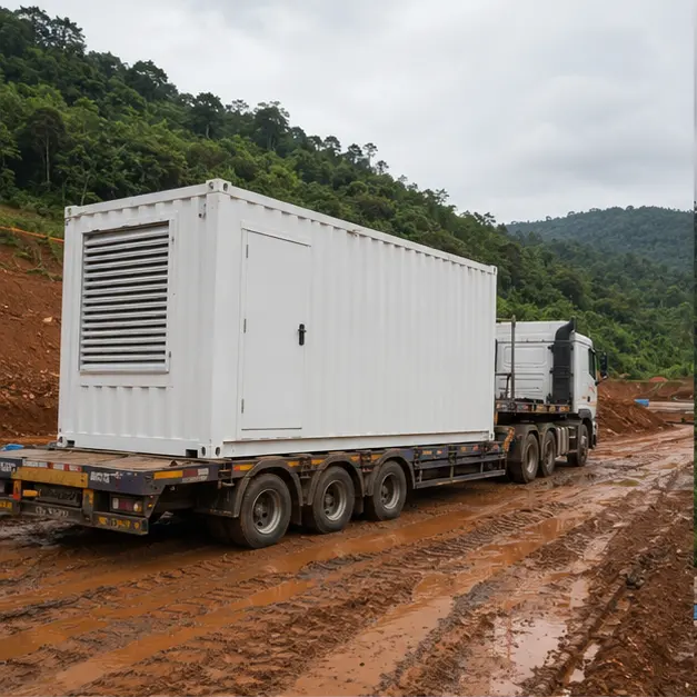
Delivery — Delivery of a containerized substation of this kind along a mine access road
Moving the unit down a wet mine road is its own transport-engineering exercise. Before the load ever leaves, axle loads, gradients, camber, the capacity of bridges and culverts, and turning radii are all checked against the route. Because a container substation stands tall for its footprint and carries its weight low and off to one side — where the transformer sits — it is lashed to stop it shifting sideways, not just held down against vertical movement. Once it arrives, the enclosure is checked for transit damage, door and louvre fit, seal integrity and any sign of water getting in, while equipment inside is checked for fixings that may have worked loose. If an oil-filled transformer is fitted, oil level and gasket condition are inspected before the delivery is signed for.
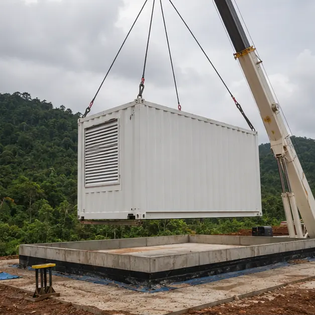
Placement — Crane lift onto a raised foundation, characteristic of a mining installation of this type
Setting the unit down on its raised base is the single highest-risk lift in the sequence. The plinth is not there for appearance: it lifts the cable entries and the enclosure floor clear of the surface water and mud a tropical mine site produces, and it gives the cable trench a fall to drain. The lift itself uses the marked corner or lug points and a spreader bar, so the slings never load the enclosure walls directly, and crane capacity is checked at the actual working radius against ground bearing pressure confirmed under the outriggers. Level is verified before the unit touches down — if it lands out of level, the door seals distort, the enclosure's IP rating is compromised, and water pools on the roof. The final anchoring follows the seismic design, not a token bolt-down.
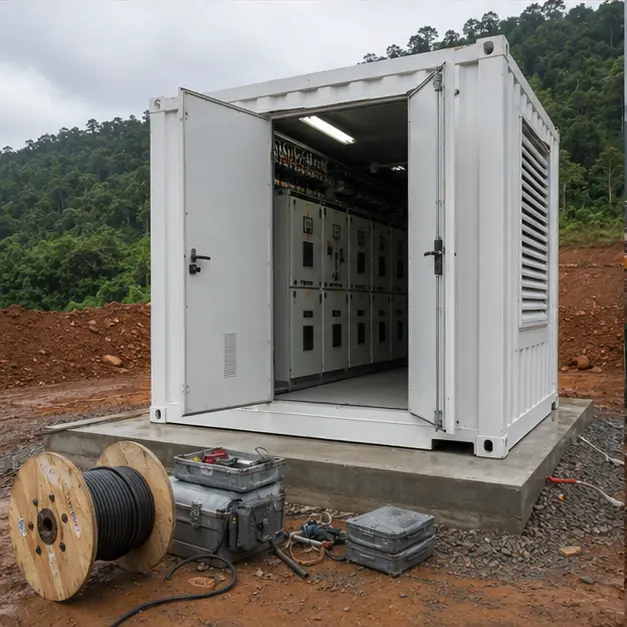
Internal work — Medium-voltage switchgear and cable termination work inside a substation container of this type
The internal work package covers MV and LV cable terminations, busbar connections and the earthing installation. MV terminations carry the most risk on the whole job — screen cut-back length, how clean the surface is, and whether the stress cone seats correctly determine whether the joint lasts, and in high humidity it makes sense to finish this work in one session rather than leave it half-done overnight. Cable screens bond to the internal earth bar through a conductor rated for the earth-fault duty. Every busbar and terminal bolt is torqued to spec and marked, because it is contact resistance, not the rated current alone, that turns a joint into a hot spot. Insulation resistance is measured, interlocks are checked by actually operating them, and the external earth electrode is connected with its resistance logged.
Completed configuration — Finished configuration of a 20 kV/0.4 kV containerized substation serving a mining and mineral-processing site
The finished layout shows the container fenced, sealed and labelled. Before power is applied the whole installation is proved end to end: transformer ratio and vector group are verified, insulation resistance is logged, earth continuity is confirmed from every part of the enclosure back to the main bar, and protection is proved by injection testing so the relay, CT circuit and trip coil are all shown to work together. Ventilation, heating and any monitoring outputs are exercised functionally. Power-up is staged — the transformer is energised unloaded first, then the LV board, then load is brought on gradually — with close attention paid to voltage dip when the largest motors start, since that is exactly the condition the impedance was chosen to handle.
Specification options
For a comparable mining enquiry, Millenium can tailor the voltage ratio and tapping range, transformer capacity, vector group and impedance to match the plant's motor-starting duty, with copper or aluminium windings. The transformer is available as cast-resin dry-type or oil-immersed with containment, with insulation class and temperature-rise limits set for the site ambient and any harmonic loading from drives. MV switching options include an SF6 or solid-insulated RMU, or an air-insulated metal-clad panel with withdrawable breakers. LV assemblies can be built to the required form of separation and short-circuit withstand rating, with motor starter or drive sections included. Enclosures can be specified by IP rating, ISO 12944 corrosion category and coating system, with filtered forced ventilation or air conditioning, anti-condensation heating, fire detection and seismic anchoring. Monitoring can be extended to temperature, status and alarm reporting over Modbus, IEC 61850 or DNP3.
What we need to quote
Single-line diagram of the site supply and the intended distribution layout
Incoming 20 kV details, including tapping range and required vector group
Outgoing LV voltage, system earthing method and the LV distribution schedule
Transformer capacity, plant load profile and the motor list with starting method and largest motor rating
Any variable-speed drive content and its expected harmonic spectrum
System fault level at the point of connection, required withstand rating and clearing time
Protection philosophy, plus any existing relay settings or grading study
Site ambient temperature range, humidity, rainfall, altitude, dust type and any corrosive process exposure
Seismic design requirement and whether the foundation is raised or at grade
Enclosure IP rating, ISO 12944 corrosion category, coating specification and internal cooling method
Communication protocol, plus the mine control system interface and points list
Site access route, permissible axle loading, available crane capacity and delivery terms
Quotation
Quote a comparable Indonesia project
Tick what you can already provide — it is added to your message — then send the inquiry. Missing items are not a problem; we will ask.