ISO 9001 · ISO 14001 · ISO 45001 · CE · UDEM · EAC · CQC
🇪🇬 Egypt · Utility transmission
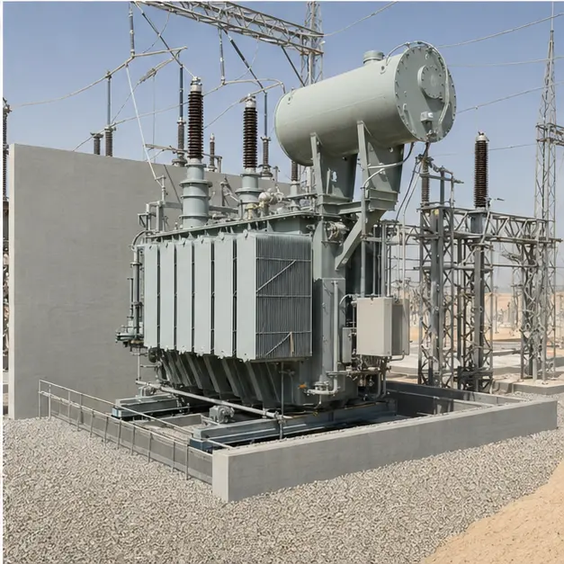
Egypt: 66 kV/11 kV Oil-Immersed Grid Transformer
Reference configuration: 66 kV/11 kV oil-immersed grid transformer with radiator cooling and on-load tap changer for utility transmission and distribution…
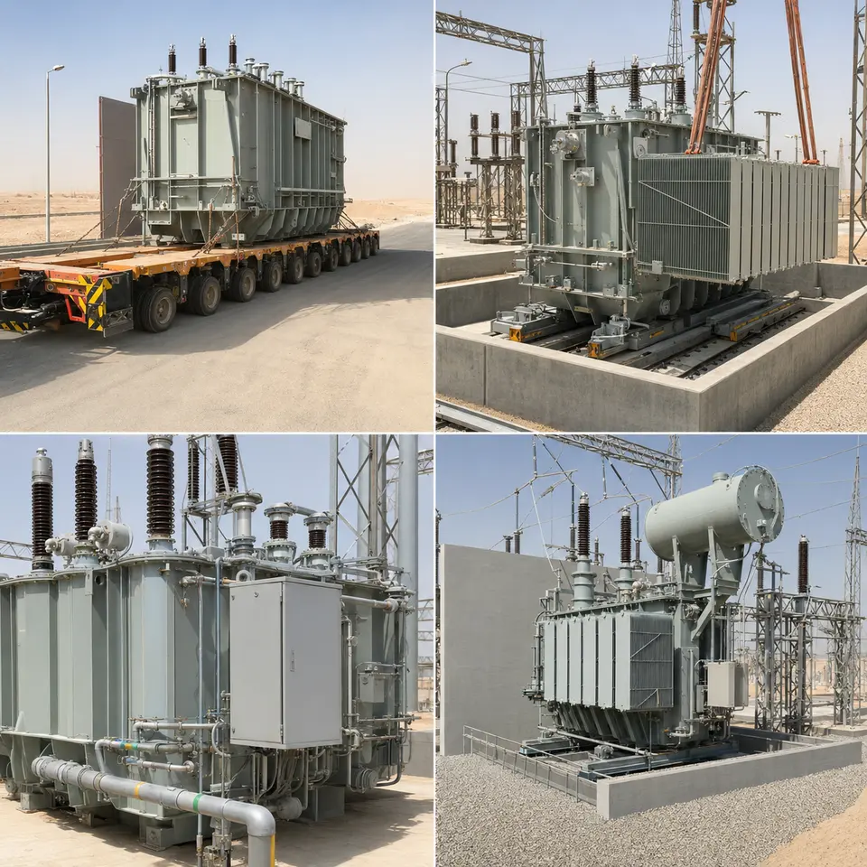
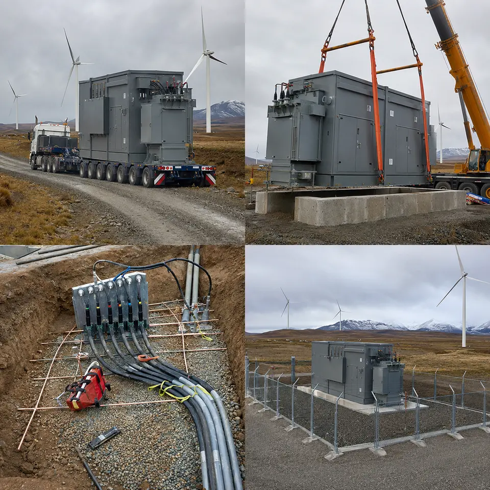
The four-stage sequence typical of a grid transformer used for 66 kV/11 kV substations in Egypt
Representative project visualisation. Representative visualisation, not a delivered installation. Every image in this set is a representative rendering of a typical build for this equipment class, not a photograph or documentary record of a completed project. None depicts an actual customer, site, utility, network owner, contract, energisation date, or third-party certification. All ratings, quantities and arrangements shown are illustrative and would be finalized against a genuine enquiry.
At a glance
Country
Egypt
Application
Utility transmission and distribution substation, desert environment
System
66 kV/11 kV oil-immersed grid transformer with radiator cooling and on-load tap changer
Voltage
66 kV primary / 11 kV secondary
Frequency
50 Hz
Standards basis
IEC 60076 series (-1 general, -2 temperature rise, -3 insulation levels and dielectric tests, -5 short-circuit withstand, -7 loading guide, -10 sound levels), IEC 60214-1 and IEC 60076-21 for tap changers, IEC 60137 for bushings, IEC 60099-4 for surge arresters, IEC 61869 for instrument transformers, IEC 60815 for pollution-related insulator selection, IEC 61936-1 and IEC 62271-202 practice for the bay and containment; the purchasing network owner's own specification would govern where it is more onerous
At 66 kV this is a sub-transmission grid transformer rather than a distribution unit, and that distinction reshapes the specification in four connected ways.
First, it has to regulate a busbar. An 11 kV bus fed from a 66 kV network needs to stay within limits even as the upstream voltage and the downstream load both shift throughout the day, so the unit needs an on-load tap changer paired with an automatic voltage regulator — off-circuit links won't do the job. The tapping range, step size and regulation band all come from a voltage study of the network at that point, and the tap changer then becomes the transformer's only moving mechanical part and its principal item of maintenance.
Second, protection has to be unit protection. A transformer at this scale and this position in the network is protected by differential relaying with vector group and ratio compensation, restricted earth fault on the windings, and Buchholz gas and surge relays that catch developing faults inside the tank before they turn electrical. Buchholz protection isn't a backup for differential protection — it picks up slow gassing that differential relaying simply never will.
Third, the oil is as much an environmental system as an insulating one. A bunded, drained containment area sized to hold the full oil volume plus firefighting water, with adequate separation from neighbouring plant, is part of the design and part of the civil works alike.
Fourth, the desert ambient is the governing design case. IEC's standard cooling-air limits are reference values only; a site that exceeds them has to be bought with either a reduced temperature rise or extra cooling surface. Sand and dust clog radiator fins, block filters and settle on bushing surfaces, which pushes up both the required creepage class and the cooling margin.
How the system is built
Item
Description
Specification notes
Main tank and active part
A three-phase oil-immersed core-type transformer, 66 kV/11 kV
Insulation levels built to IEC 60076-3 for the 66 kV system; short-circuit withstand demonstrated to IEC 60076-5 against the network's actual fault level; core flux density set for 50 Hz operation, so a 60 Hz-designed unit is not a drop-in substitute
Cooling
Detachable radiator banks, ONAN or ONAF with staged fans
Rating declared at the site's actual design ambient rather than the standard reference ambient; fin spacing and filtration selected against airborne sand; fans staged from oil and winding temperature
On-load tap changer
Diverter and selector assembly with motor drive, automatic voltage regulator and remote indication
Tapping range and step size derived from the voltage regulation study; a separate OLTC oil compartment with its own conservator section and dedicated protective relay; operation counter and mechanism heating included
Conservator and oil preservation
A conservator using rubber diaphragm or air-cell separation, with a dehydrating breather
Sealed preservation keeps atmospheric moisture out of the oil, which matters where large daily temperature swings drive substantial breathing volumes; breather condition is checked as a routine inspection point
Bushings and terminations
66 kV HV bushings, 11 kV MV bushings, and a neutral bushing
Creepage distance chosen under IEC 60815 for the site's pollution class, since desert dust combined with morning condensation is conductive; bushing type, mounting angle and clearance coordinated with the bay layout
Surge protection
Metal-oxide surge arresters on both the HV and MV sides
Rated and continuous operating voltage set from the system earthing arrangement; arrester leads kept short and directly bonded, since lead inductance can defeat an otherwise correctly rated arrester
Protection and monitoring
Differential and restricted earth fault protection, Buchholz gas and oil-surge relays, pressure relief device, oil and winding temperature indicators, oil level gauge
CT ratios and vector group compensation set at the relay; Buchholz alarm and trip stages wired separately; winding temperature measured by thermal image with fan and alarm contacts; optional online dissolved gas monitoring
Oil containment
A bunded, drained containment pit beneath the transformer, with separator and firefighting provision
Capacity covers the full oil volume plus water; separation distances and any firewall follow the practice adopted for the bay
Auxiliaries and interfaces
Marshalling kiosk, control and alarm wiring, anti-condensation heating, communication gateway
Kiosk IP rating and gasketing specified against sand ingress; interfaces to the substation control system over IEC 61850, IEC 60870-5-104 or Modbus as the scheme requires
Sequence of works on site
Overview — The four-stage sequence typical of a grid transformer used for 66 kV/11 kV substations in Egypt
This contact sheet steps through the four stages typical of an installation of this kind: multi-axle heavy transport, placement and radiator assembly, bushing and auxiliary connection, and the finished transformer bay. The sequence follows what the tank itself will allow. The unit travels without its radiators, conservator and often its bushings, so those go on after placement. Oil work follows once mechanical assembly is complete, and the tank is never left open to desert air beyond its exposure limit. Electrical testing waits until after oil filling and the standstill period that lets entrained gas clear, and the bay is closed up and the containment finished only once the unit has been proved.
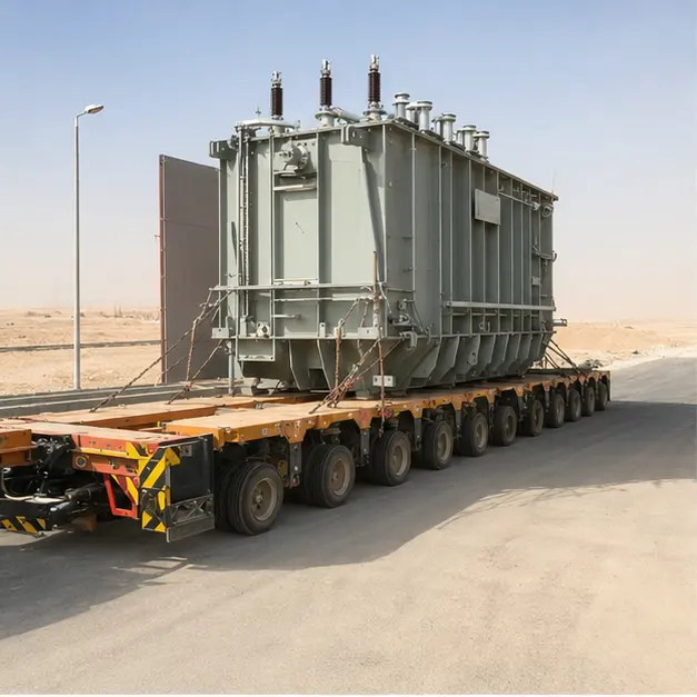
Delivery — Multi-axle heavy transport of an oil-immersed grid transformer of this type on a desert road
A 66 kV transformer moves as an indivisible load on a multi-axle trailer, with the route engineered before the unit ever leaves the works. Axle loading, bridge and culvert capacity, gradient, camber, overhead clearance and turning radii are all surveyed, and desert road sections are checked for bearing capacity wherever the shoulder looks soft. The tank travels braced, usually filled with dry air or nitrogen held at a positive pressure that's logged along the whole route, and fitted with impact recorders on more than one axis. On arrival, those readings are downloaded and compared against the accepted limit before the unit is off-loaded — an over-limit impact is grounds to inspect the active part rather than simply proceed. Gas pressure, dew point, and the condition of blanking plates and valves are checked and recorded at handover.
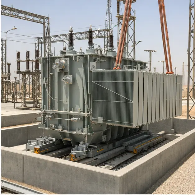
Placement and assembly — Radiator bank assembly and placement of a grid transformer of this configuration
Placement uses the designated jacking pads and lifting lugs, with the lift planned around a centre of gravity that sits high and shifts further once the tank is filled. The plinth and rails are confirmed level, since an out-of-level tank throws off oil level indication and can leave a radiator bank only partly filled. Wheels or rails are then locked and the unit anchored to the seismic and wind detail specified for the bay. Radiator banks, conservator and pipework are assembled onto the tank with fresh gaskets, and valve positions are checked and logged — a closed radiator valve is one of the more common causes of an overheating transformer in service. Oil is filled under vacuum through a treatment plant, with moisture content, breakdown voltage and dissolved gas sampled before and after, and the assembly is then left to stand so entrained air can escape before any voltage is applied.
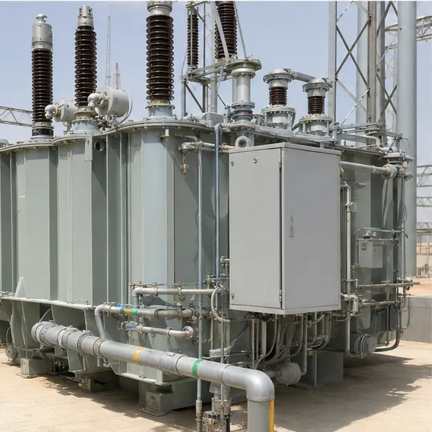
Connection — High-voltage bushings, surge arresters and auxiliary connections on a transformer of this type
Fitting the bushings is precision work. Each one is checked for transport damage, oil level, and capacitance and tan-delta values against its test certificate, then fitted with correct gasket compression and torque sequence, with the draw-lead or connection made without twisting the internal conductor. Clearances from live terminals to earthed structure, and between phases, are measured on the as-built arrangement. Surge arresters are mounted with the shortest practicable earth lead run directly to the bay earth grid. Auxiliary work covers the Buchholz relay's mounting angle and pipe gradient — it won't function correctly on a level pipe run — the pressure relief device, oil and winding temperature indicators with their capillaries shielded from direct sun, the tap changer drive with its limit and interlock settings, and the marshalling kiosk with its heating, sealing and cable gland arrangement.
Completed configuration — A completed configuration of a 66 kV/11 kV grid transformer bay with radiator cooling and oil containment
The finished configuration shows the transformer standing in a fenced bay over its containment pit, with radiators, conservator, arresters and marshalling kiosk all in place. Before energisation the unit is proved link by link: insulation resistance and polarisation index, winding resistance on every tap, turns ratio and vector group on every tap, magnetising current, and capacitance and tan-delta on windings and bushings, plus a final oil sample for moisture, breakdown voltage and dissolved gas that becomes the baseline for every future sample. Protection is proved end-to-end by injection, with differential stability checked and the Buchholz alarm and trip paths proved separately. The tap changer is run through its full range under supervision and its counter reading logged. Energisation is staged, with the unit charged unloaded, inspected, and left to soak before any load is applied.
Ways the specification can flex
For a comparable utility enquiry, Millenium can develop a grid transformer around the required capacity, impedance and impedance tolerance, vector group and neutral arrangement, with the tapping range, step size and regulation band set from the voltage study. Cooling can be ONAN, ONAF or ONAN/ONAF dual-rated, with fan staging defined and the rating declared at a stated site ambient rather than a reference ambient. On-load or off-circuit tap changing can be supplied, with an automatic voltage regulator, parallel-operation scheme and remote indication. Bushing creepage class can be matched to the site pollution level, with surge arresters coordinated to the system earthing. Protection and monitoring can extend from conventional differential, restricted earth fault, Buchholz and temperature devices up to online dissolved gas and bushing monitoring, reporting over IEC 61850, IEC 60870-5-104 or Modbus. Loss capitalisation, sound level limits, containment arrangement, and paint and corrosion class can all be specified to suit.
Information we need to quote this
A single-line diagram of the substation showing the transformer's position in it
Rated capacity, the ONAN and ONAF ratings required, and the loading profile including any cyclic or emergency overload duty
The required impedance and its tolerance, vector group, and neutral earthing arrangement
Tapping range, step size, regulation band, and whether on-load or off-circuit tap changing is wanted
System fault level on both sides, the required short-circuit withstand duration, and the applicable insulation levels
Protection philosophy, relay types, CT ratios, and the interlocking and alarm schedule
Communication protocol and the substation control system's points list
Site ambient temperature range including the design maximum, altitude, solar radiation, and sand or dust pollution class
The loss evaluation or capitalisation formula, and any sound level limit at a stated distance
Bay layout, containment pit arrangement, separation distances, and any firewall requirement
Paint system, corrosion category, and any specific colour or marking requirement
Transport route survey, permissible axle loading, crane capacity available, and delivery and site-service terms
Speak with us
Shanghai Millenium Industry Co., Ltd. (Millenium) — No. 555 Gangding Road, Lin-gang Special Area, China (Shanghai) Pilot Free Trade Zone, Shanghai, China.
Tel/WhatsApp/WeChat +86 175 0213 9434 · jensen@millenium-electric.com · millenium-electric.com
Every image in this document is a representative visualization of a typical configuration — not documentary evidence of a completed project.
Quotation
Quote a comparable Egypt project
Tick what you can already provide — it is added to your message — then send the inquiry. Missing items are not a problem; we will ask.