ISO 9001 · ISO 14001 · ISO 45001 · CE · UDEM · EAC · CQC
🇦🇺 Australia · Energy storage
Australia: 5 MWh Liquid-Cooled Containerized BESS
Reference configuration: 5 MWh liquid-cooled containerized battery energy storage system with PCS and 22 kV step-up transformer for solar-farm energy storage…
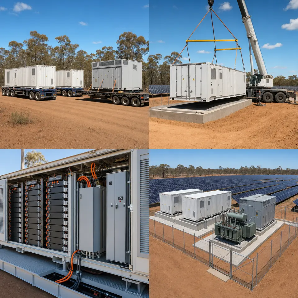
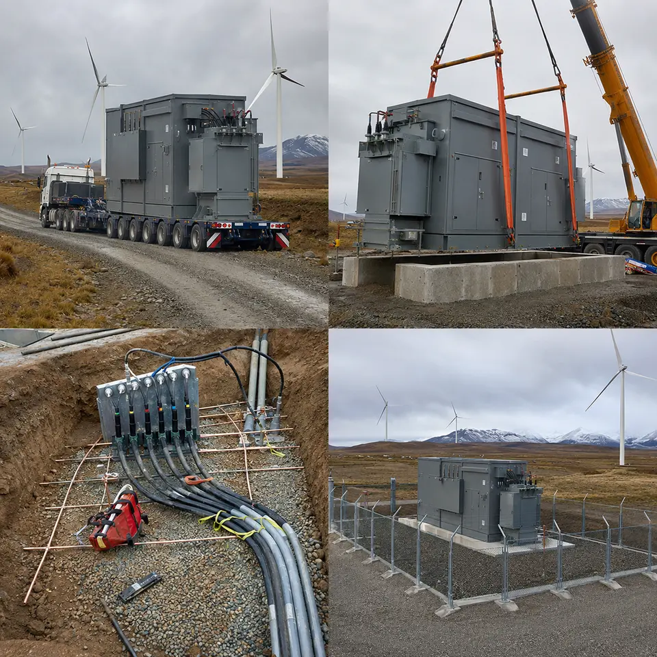
Four-stage sequence typical of a liquid-cooled containerized BESS installed beside solar plant in Australia
Representative project visualisation. Every image in this set is a representative visualisation of a typical build of this equipment class — none of them is a photograph or documentary record of a completed job, and none stands in for any specific customer, site, operator, network service provider, contract, commissioning date, or third-party sign-off. The ratings, quantities and layout shown here are illustrative starting points that would be pinned down against an actual enquiry.
At a glance
Country
Australia
Location
Inland New South Wales (as stated in the source material)
Application
Solar-farm energy storage and grid support
System
5 MWh liquid-cooled containerized battery energy storage system with PCS and 22 kV step-up transformer
Voltage
Battery DC bus to PCS; 22 kV medium-voltage connection
Frequency
50 Hz
Standards basis
AS 60076 series with the older AS 2374 series still referenced for transformers, AS 2067 for installations above 1 kV, AS/NZS 3000 Wiring Rules for the low-voltage installation, AS/NZS 5139 for battery system safety, AS/NZS 4777.2 for inverters within its scope and the National Electricity Rules generating-system performance standards above it, AS/NZS 61439 for LV assemblies, AS/NZS 1170 for wind and structural loading, AS 3959 practice where the site is bushfire prone, UN 38.3 and the Australian Dangerous Goods Code for transport
Three forces shape a storage system built for this market, and only two of them are electrical.
The first is the grid interface. A 5 MWh system connecting at 22 kV inside the National Electricity Market sits above the point where AS/NZS 4777.2 alone governs, so its behaviour instead gets fixed through negotiated generating-system performance standards agreed with the network service provider and AEMO — covering reactive capability, voltage and frequency ride-through, active power control, power quality and protection settings. The mainland frequency operating standard keeps a tight normal band, roughly ±0.15 Hz, and the frequency control ancillary services markets exist to pay for response delivered inside that band. Whether the plant needs to be grid-following or grid-forming, and what response times it must hit, is therefore something that shapes PCS choice at the enquiry stage, well before commissioning.
The second is climate. Inland New South Wales summers push ambient temperatures above the point where air-cooled equipment starts losing rated output, and the daily temperature swing is large. Liquid cooling keeps cells within a tighter band and rejects heat more effectively than forced air, but chiller capacity itself drops as condenser inlet temperature climbs, so design has to use the site's actual ambient rather than a generic figure. On top of that, dust clogs heat exchangers, UV attacks polymers and cable sheathing, and bushfire exposure dictates vegetation clearance, asset protection zones and the overall fire-protection approach.
The third factor is regulatory, and it is worth stating outright because it determines who is legally able to sell the system. RCM marking under the Electrical Equipment Safety System requires a local Australian Responsible Supplier — usually the importer — registered in the national database, and Millenium cannot hold that registration from outside Australia. GEMS registration follows the same pattern wherever a transformer falls under minimum energy performance requirements: the registrant has to be an Australian entity. Millenium's role is to supply the equipment along with the test evidence and technical documentation behind it; the Australian importer or first supplier is the one who holds the registration and applies the mark.
System configuration
Item
Description
Specification notes
Battery container
Containerized enclosure housing racks, thermal management, fire protection and controls
Ingress and corrosion protection specified for inland heat, dust and UV; structural design to AS/NZS 1170 wind loading; separation distances and asset protection zone set at layout stage
Battery racks and modules
Lithium modules in racks with rack-level disconnection and fusing
System safety arrangement to AS/NZS 5139; module, rack and system-level monitoring of voltage, current and temperature; rack isolation accessible without entering an energised aisle
Battery management
Three-level BMS — module, rack and system — with contactor control and protection
Cell balancing, state of charge and state of health estimation, and hard protection limits that act independently of the site controller
Liquid cooling
Chiller, pumps, manifolds and rack cold plates on a water-glycol loop
Chiller capacity declared at the site design ambient, not a nominal one; coolant concentration set for both the summer duty and the coldest inland nights; leak detection, pump redundancy, flow and temperature monitoring, and delta-T across racks controlled to limit cell-to-cell divergence
PCS
Bidirectional conversion between the battery DC bus and the AC system
Grid-following or grid-forming as the connection requires; reactive capability, ride-through, active power control and frequency response functions demonstrated against the negotiated performance standards
Step-up transformer
Transformer between PCS output and the 22 kV connection
AS 60076 / AS 2374 basis with any applicable minimum energy performance requirement; cast-resin dry-type where fire load governs, or oil-immersed with containment; impedance matched to the PCS and to the network fault level
MV switchgear and protection
22 kV switching, connection-point protection and metering
Protection settings and any anti-islanding or transfer-trip requirement per the network service provider; metering arrangement per the connection agreement and market registration
Fire detection and protection
Gas, smoke and heat detection, alarm, deflagration venting and the agreed suppression or containment strategy
Detection aimed at off-gassing ahead of thermal runaway; emergency shutdown interlocked with BMS and PCS; access, water supply and clearance arrangements agreed with the fire authority
Control and communication
Site controller with interfaces to the solar plant, the network service provider and the market
Modbus TCP, IEC 61850 or DNP3; telemetry, dispatch and remote control to the extent the connection agreement and market registration require
Installation sequence
Overview — Four-stage sequence typical of a liquid-cooled containerized BESS installed beside solar plant in Australia
The contact sheet lays out four stages typical of this kind of installation: container and PCS delivery, crane placement on the prepared foundation, inspection of battery racks and the cooling system, and the finished, fenced installation with its 22 kV step-up transformer. Sequencing follows what becomes hardest to reach later. Foundation, cable ducts, earth grid and drainage are finished and surveyed before any container is landed. Cabling between container, PCS and transformer is measured against the positions as actually built. Coolant filling, leak testing and the first controlled charge all come after mechanical and electrical work wraps up, and the site is only closed once the fire detection and emergency shutdown chain has been proved out.
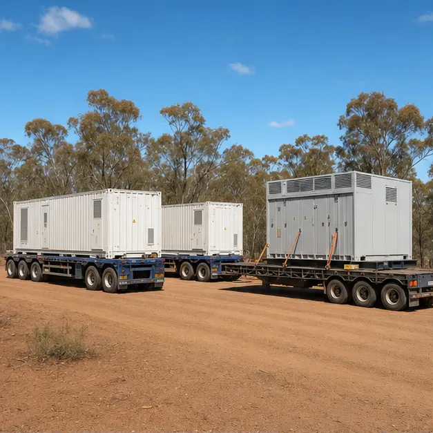
Delivery — Delivery of battery storage containers and PCS equipment of this type to an inland solar site
A battery container travels as dangerous goods. Cells move under UN 38.3 test certification and, on Australian roads, under the Australian Dangerous Goods Code — typically at a restricted state of charge with the system electrically isolated — so documentation, labelling and transport state of charge get checked on arrival just as carefully as the hardware itself. Long inland routes are assessed for axle loading, gradients, culvert and bridge capacity, headroom and turning radii, plus whatever unsealed final approach the solar site presents. On arrival, containers and PCS units are inspected for transport damage, seal and louvre condition, water and dust ingress, shock-indicator status and shifted internal fixings; racks are checked for module movement and connector integrity, and the coolant circuit is examined before anything is pressurised.
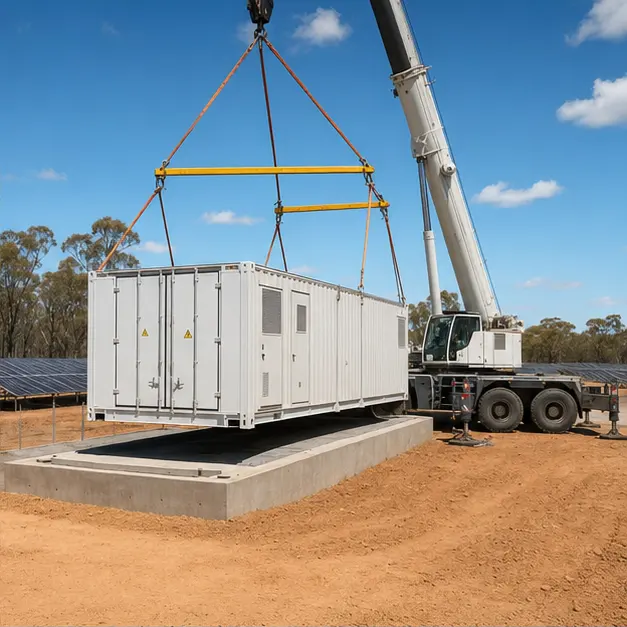
Placement — Crane placement of a battery storage container onto a prepared foundation, typical of an installation of this type
Placement is one lift of a heavy, tall, evenly loaded unit. The lift uses designated corner castings or lugs with a spreader beam so slings never bear on walls, doors or roof-mounted cooling plant. Crane capacity is assessed at working radius and derated for wind on an exposed inland site, with outrigger bearing pressure checked against ground that may be dry crust over softer material below. Level is confirmed before the container is set down — with liquid cooling, level is a functional requirement, not just a nicety, since an out-of-level container traps air in the coolant circuit and biases flow between racks. Separation distances to other containers, to the transformer, to boundaries and to vegetation are checked against the fire-protection and bushfire layout before anchoring is finished to the wind-loading detail.
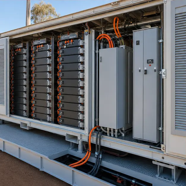
Internal work — Battery racks and liquid-cooling arrangement typical of a container of this configuration
Internal work covers DC connections, the coolant circuit, and the control and safety wiring. Rack DC joints are torqued to the specified value and marked, because a high-resistance joint on a DC bus carrying continuous current is both an energy loss and a fire risk — a DC arc, unlike AC, does not self-extinguish at a current zero. Polarity, rack isolation and fuse ratings are all verified before any rack is closed up. The coolant circuit is filled with the specified water-glycol mixture, vented, pressure-tested and run to confirm flow reaches every rack, since uneven flow shows up as cell-to-cell temperature divergence — something that shortens life and is hard to fix afterward. Leak detection, coolant flow and temperature monitoring, and the gas, smoke and heat detection loops are all functionally proved, including how they act on the BMS and PCS.
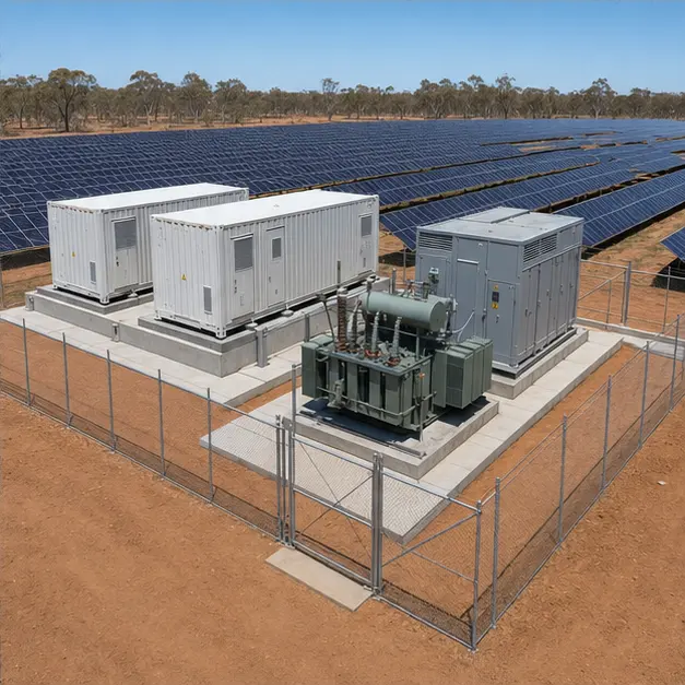
Completed configuration — Completed configuration of a 5 MWh liquid-cooled BESS with a 22 kV step-up transformer beside a solar plant
The finished configuration shows the containers, PCS and 22 kV step-up transformer sitting inside a fenced compound next to the solar plant. Ahead of energisation the installation is proved end to end: transformer ratio and vector group checked on every tap, insulation resistance recorded, earth continuity confirmed from every enclosure back to the earth grid, and grid resistance measured. Connection-point protection is proved by injection across the full chain, and the anti-islanding or transfer-trip path is demonstrated. Commissioning then turns to the grid interface: controlled charge and discharge, reactive capability across the required range, ride-through and frequency response behaviour, and the telemetry and dispatch path to the network service provider and the market. Evidence gathered at this stage supports the performance-standard demonstration, while RCM and any GEMS registration remain the responsibility of the Australian party holding them.
Specification options
For a comparable Australian enquiry, Millenium can configure energy and power rating, C-rate and cycle-life expectation, cell chemistry and rack architecture, with the BMS hierarchy and protection limits defined to suit. Thermal management can be liquid or forced air, with chiller capacity, coolant chemistry and concentration declared at the site's design ambient. PCS can run grid-following or grid-forming, built around whatever reactive capability, ride-through and frequency response functions the connection calls for. The step-up transformer is available as cast-resin dry-type or oil-immersed with containment, at the required voltage ratio, vector group and impedance. Enclosures can be specified for IP rating, corrosion category, coating class, UV resistance and wind loading, with the fire detection, venting and suppression concept agreed against the site. Control and telemetry run over Modbus TCP, IEC 61850 or DNP3. RCM and GEMS registration stay with the Australian importer or responsible supplier; Millenium provides the supporting test evidence and technical documentation.
What we need to quote
Single-line diagram of the solar plant, the storage system and the 22 kV connection point
Required energy and power rating, C-rate, daily cycle count and expected service life
Connection voltage, network fault level and the network service provider's connection requirements
Negotiated or proposed generating-system performance standards, including reactive capability, ride-through and frequency response obligations
Intended market services — energy shifting, peak management, contingency or regulation FCAS — and any grid-forming requirement
Protection philosophy at the connection point, including anti-islanding or transfer-trip arrangements
Site design ambient temperature range, altitude, dust exposure, UV and wind region for structural loading
Bushfire exposure, asset protection zone, vegetation clearance and the fire authority's requirements
Fire detection, venting and suppression concept, and separation distances available on the site layout
Foundation arrangement, site access route, permissible axle loading and available crane capacity
Communication protocol, SCADA points list and metering and market registration arrangements
Which Australian entity will act as responsible supplier for RCM, and the GEMS registration route for the transformer, together with delivery terms
Quotation
Quote a comparable Australia project
Tick what you can already provide — it is added to your message — then send the inquiry. Missing items are not a problem; we will ask.